Вопросы и ответы: Virtual Switching System (VSS) и ее реализация на платформах Cisco Catalyst 4500 и 6500

Во время прямой трансляции эксперт Cisco Александр Нестеров рассмотрит основы технологии виртуализации коммутации Virtual Switching System (VSS). Александр расскажет о ее возможностях и преимуществах. Также будут приведены примеры реализации VSS на двух многоуровневых модульных коммутационных платформах Cisco Catalyst 6500 и 4500.
Вопросы и ответы
A: Изначально был VSS. По большому счету vPC пошел многим дальше в свой реализации.
Q: VSS между разными шасси 6500 возможен?
A: Если говорить о количестве слотов в платформах, то это не должно быть проблемой. Самое главное в данном случае PFC/DFC.
Q: На Cisco 6509E возможно реализовать VSS?
A: Да, такое шасси использовать возможно.
Q: Линки для соединения коммутаторов нужно делать через порты супервизора или любые коммутируемые порты?
A: Для VSL линка, обязательным параметром является использование 10Gb/s канала. Т.о. это могут быть порты и линейной карты.
Q: Будет ли работать VSS между 6500 и 4500?
Q: В домене VSS может быть только 2 устройства?
A: Только два. Но в защиту рещения можно сказать, что в шасси может быть по два сепурвизора.
Q: Для двухпортового VSL создается Port Channel?
A: Port-channel создается всегда, даже в том случае, если только один линк используется для VSL. Более того, ввиду виграции конфигов (что вы увидете дальше) эти port-channel будут различными на обоих устройствах.
Q: Можно ли «на горячую» добавлять линки в имеющуюся VSL?
Q: Т.е. в VSL используется только 1 физический линк? Даже если активных линков 8?
Q: Какая версия IOS должна быть на обоих супервизорах для совместной работы? Могут ли супервизоры работать на разных версиях IOS?
A: Начиная с 12.2(33)SXH. Разные версии приводят с режиму RPR.
Q: Поддерживается ли Quad-Sup (4 супервизора на систему) для платформы 2Т? Если да, то начиная с какой версии Cisco IOS?
Q: Какой смысл в 4 супервизорах? Только резервирование?
A: Второй супервизор, может быть использован для передачи трафика (иначе говоря, дополнительная пропускная способность/каналы), таким образ все 4 супервизора будут передавать трафик.
Q: Может ли возникнуть ситуация, когда в результате распределения, часть потоков отправится через VSL?
Q: Планируется ли поддержка VSLP Fast Hello на 4500 платформах?
A: Насколько мне известно это будет представлено в следующем релизе.
Q: Т.е., если на севере от VSS стоит файловый сервер, подключеный только к одному VSS-member, а на юге от VSS стоит access-коммутатор, включеннный по MEC, то весь трафик от сервера будет отправлен только через один канал MEC (предположим, что MEC из 2-х линков)?
A: Нет трафик будет хешироваться на 2 линка внутри MEC.
Q: В чем разница между технологиями VSS на 4500 6500?
A: С точки зрения конечного пользователя разницы нет. Нужно понимать, что платформы используют абсолютно разную логику передачи данных (4500 все-таки централизированная платформа, в то время как 6500 распределенная).
Q: Можно ли использовать для ePAgP коммутаторы 2960?
Q: VSS-кластер поддерживает все имеющиеся на платформе возможности или есть какие-либо ограничения?
A: Да, пожжерживаются все возможности.
Q: Если при разрыве VSL-линка, находясь в ситуации Dual Active, произошло изменение конфигурации на standby-коммутаторе, то при восстановлении VSL-Линка VSS не соберется?
A: Конфигурация будет загружена с Active коммутатора.
Q: В случае Quad-Sup для VSL надо использовать порты только на супервизорах?
A: Это не обязательное требование.
Q: Переключение с Active SUP на Standby SUP не ведёт к потере трафика?
A: По большому счету не ведет, однако минимальная потеря трафика имеет место быть.
Cisco VSS: страх и ненависть на работе
Данный пост я написал в порыве негодования и недоумения от того, как сетевое оборудование от мирового лидера в данном сегменте может сильно и неожиданно портить жизнь production-процессам и нам – сетевым админам.
Я работаю в государственной организации. Ядром нашей сетевой инфраструктуры является VSS-пара, собранная из двух коммутаторов Cisco Catalyst 6509E под управлением супервизоров VS-S720-10G-3C с версией IOS 12.2-33.SXI6 (s72033-adventerprisek9_wan-mz.122-33.SXI6.bin) на борту. Наша сетевая инфраструктура является полностью production и должна быть доступна практически 24*7*365. Какие-либо профилактические работы, предполагающие малейший останов предоставляемых сервисов, мы должны заранее согласовывать и выполнять в ночное время. Чаще всего это ночные квартальные профилактики. Об одной из таких профилактик я хочу рассказать. И я искренне не хочу, чтобы с вами повторилась моя история.
Сразу обозначу начинку одного из коммутаторов VSS пары (начинка второго коммутатора идентична):

На эту профилактику были запланированы, казалось бы, совершенно рутинные операции. Нам было выделено окно с 2 часов ночи до 8 утра. Это значит, что в 8 утра все должно быть агонь! работать. Я приведу хронологию событий той романтической ночи:
1. Включение поддержки jumbo frames на VSS-паре Cisco catalyst 6509E. Все команды взяты из официального руководства Cisco:
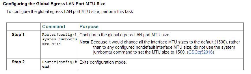
# conf t
# system jumbomtu
# wr mem
На сайте CISCO сказано, что некоторые линейные карты не поддерживают jumbo frames вовсе, либо поддерживают ограниченный размер пакетов:
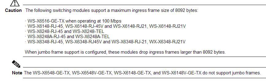
Мои линейные карты в этот список не попали. Отлично.
2. Также была включена поддержка jumbo frames еще на нескольких, стеках (catalyst 3750E, 3750X), смотрящих в VSS. Но это, на мой взгляд, мало имеет отношения к ниже описанной ситуации.
На данном этапе все было штатно. Полет нормальный. Едем дальше.
3. Далее, по плану была плановая чистка коммутаторов catalyst 6509E от пыли методом пылесоса. Эту операцию мы делаем регулярно (раз в квартал) и ничего неестественного мы не ждали. Решили начать с коммутатора, имеющего на тот момент active virtual switch member role, чтобы заодно проверить корректное выполнение switchover. Назову его коммутатор (1). Итак, коммутатор (1) выключили. Switchover произошел корректно – второй коммутатор (2) отрапортовал, что теперь он стал active. По пингу потерялся лишь один пакет. Далее, вынули и пропылесосили Fan Tray и оба блока питания. Вставили обратно. На данном этапе мониторинг рапортовал, что сеть работает исправно – все железки доступны. Отлично, подумал я, включил коммутатор (1) и отправился за комп ждать т.к. загрузка 6509 занимает порядка 7-8 минут. Проходит 10-15-20 минут, а все лампочки на супервизоре рыжие, линейные карты погашены и второй активный коммутатор (2) по-прежнему не видит первого (#sho swi vir red). Выключил коммутатор (1). Включил снова. Опять проходит порядка 20 минут – ситуация повторяется. В это время у меня рядом не было ноута с консольным кабелем, чтобы посмотреть что происходит. Сеть по-прежнему «летит на одном крыле» — коммутаторе (2).
Здесь правильным решением стало бы взять ноут, подключиться к консоли коммутатора (1) и посмотреть — что же там происходит? Но я, подумав на конфликт нод, решил погасить 2й коммутатор, подключить ноут к консоли первого и попробовать его включить в одиночку. В консоли я увидел следующее – коммутатор (1) вывалился в rommon. Без единой ошибки. Просто rommon. Еще раз выключил — включил – сразу rommon и все. А на часах 7й час утра и меньше чем через 2 часа начинается рабочий день. Обстановка накаляется. Я решил, что экспериментировать и пробовать загрузить IOS из rommon’а не стоит. Выключил коммутатор (1). И отправился включать второй коммутатор, думая себе – ну ладно, день полетим на одном крыле, а следующей ночью разберусь с проблемой. Воткнулся в консоль, включил и… что-то пошло не так в консоли я вижу как после полной, казалось, корректной загрузки коммутатор судорожно начинает гасить по очереди все порты и уходить в перезагрузку. Так повторялось 3 раза. И только с третьего раза он с горем пополам загрузился и предложил ввести учетные данные. Залогинился. Сеть вроде работает. Выдохнул. Но не тут-то было — враги наступали в мониторинге несколько access-коммутаторов то становились доступными, то уходили в «даун». Часть серверов также «моргала». Разные ресурсы из разных VLAN частично были не доступны. Перестал корректно работать DNS в соседние сети. Я не понимал в чем дело. Закономерность не прослеживалась. Время на часах близится к 8 часам. Уселся читать логи, а там красота то какая, ляпотааа шквал повторяющихся ошибок вида:
%DIAG-SW2_SP-3-MAJOR: Switch 2 Module 5: Online Diagnostics detected a Major Error. Please use ‘show diagnostic result ‘ to see test results.
%DIAG-SW2_SP-3-MINOR: Switch 2 Module 2: Online Diagnostics detected a Minor Error. Please use ‘show diagnostic result ‘ to see test results.
Здесь Module 5 – это супервизор SUP-720-10G-3C, а Module 2 – это линейная карта WS-X6708-10GE.
Немедленно в компанию, с которой у нас заключен сервисный договор на обслуживание, мы отправили все логи, а также show tech-support и show diagnostic. Те, в свою очередь открыли кейс в Cisco TAC. И уже через 3 часа пришел ответ от Cisco TAC, что ОБА (. ) супервизора и линейная карта _аппартно_неисправны_ и подлежат замене. Бинго! Проанализировав логи, инженеры Cisco TAC сообщили, что супервизоры были уже неисправны до перезагрузки. А во время перезагрузки из-за неисправностей не смогли пройти Self tests и возобновить корректную работу. На наш вопрос о том, каким образом мы ранее могли узнать о неисправности супервизоров и, соответственно, зная об этом, не перезагружать их — нам не ответили.
К нам выехал инженер с одним (потому что на этот момент больше у них в наличии не было) подменным супом и линейной картой.
Тем временем, проанализировав ситуацию, мы поняли, что клиенты, которые испытывают проблемы с сетью, воткнуты именно в эту линейную карту. Клиентов перевесили на другие порты. До конца рабочего дня худо-бедно долетели. После окончания рабочего дня на новый подменный SUP-720-10G-3СXL с помощью флешки был залит конфиг, vlan.dat и новая версия IOS 12.2 (33) SXJ6. И было решено начать с шасси (1) – того, которое было на данный момент выключено. Заменили суп, вытащили все трансиверы (на всякий случай), завели шасси – ошибок нет. После этого погасили работающее шасси (2) и вставили трансиверы в шасси (1) – сеть ожила на одном починенном крыле с временно предоставленным SUP-720-10G-3CXL.
Обращаю внимание, что VSS не заводится между двумя разными супами: SUP-720-10G-3CXL и SUP-720-10G-3C ругаясь на:
02:16:21 MSK: %PFREDUN-SW1_SP-4-PFC_MISMATCH: Active PFC is PFC3CXL and Other PFC PFC3C
Поэтому это было временное решение-костыль до того момента как нам привезут два одинаковых SUP-720-10G-3C.
Поскольку оставлять production-сеть на долго на «одном крыле» не вариант совсем, то в ближайшее время было согласовано еще одно ночное окно для замены супа и линейной карты в шасси(2). К этому моменту на площадку привезли 2 новых SUP-720-10G-3C и линейную карту WS-X6708-10GE. По старому сценарию на новые супы были залиты прошивка, vlan.dat и свежий конфиг с уже работающего шасси (1). От шасси (2) были отсоединены все трансиверы от греха подальше. Убедились, что шасси (2) на новом железе грузится без ошибок, выключили. Скоммутировали VSL-линки, включили. Полет нормальный. VSS собрался. Воткнули трансиверы и сеть зажила на обоих крыльях. Радости не было предела. УРА! Наконец-то закончился этот кошмар.
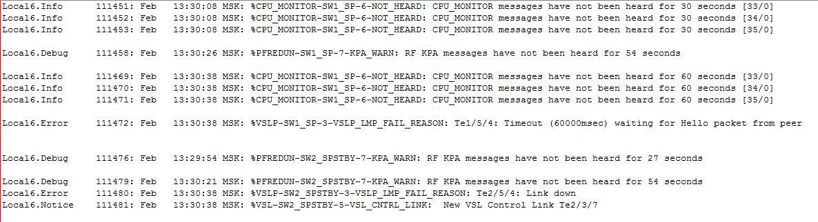
Но радость продолжалась не долго. Через несколько дней после этих работ в разгар рабочего дня внезапно гаснет VSL-линк между супами. Что за чертовщина? На новом оборудовании? Благо второй VSL-линк (на каждом шасси собран Port-channel LACP из двух портов для суммарного VSL-линка между шасси) между линейными картами жил и Dual Active Detection обошел нас стороной. Методом замены трансиверов 10Gbase-LRM и перестановки в соседние слоты было выявлено, что умер слот в шасси супервизора (1) – АХТУНГ!
В логах:
Далее, процедура открытия кейса в Cisco TAC и последующий ответ CISCO-инженера:
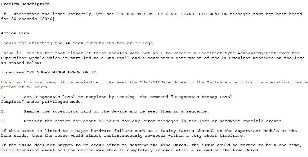
Для тех, у кого сложности с английским коротко опишу его ответ. Инженер Cisco TAC предлагает включить diagnostic bootup level complete, «передернуть» супервизор в шасси и наблюдать за развитием событий. Если это связано с Faulty Fabric Channel on Supervisor Module or the Line cards (с неисправным каналом фабрики коммутации на супервизоре или линейной карте), то проблема проявится вскоре через довольно короткое время. Если проблема не проявится по истечению 48 часов, то ее можно считать “…termed to be a one time” т.е. одноразовой.
Сейчас мы согласовываем очередное окно для выполнения данных работ. Напишу здесь обновление по результатам.
Надеюсь, что эта статья поможет кому-нибудь в трудной ситуации или предостережет от нее. На все вопросы с удовольствием отвечу в комментариях.
Всем крепких супервизоровнервов в нашей, порой захватывающей дух, профессии 🙂
Cisco 6500 VSS configuration
The Cisco Catalyst 6500 Series Virtual Switching System (VSS) allows the clustering of two chassis together into a single, logical entity. This technology allows for enhancements in all areas of network design, including high availability, scalability, management, and maintenance.
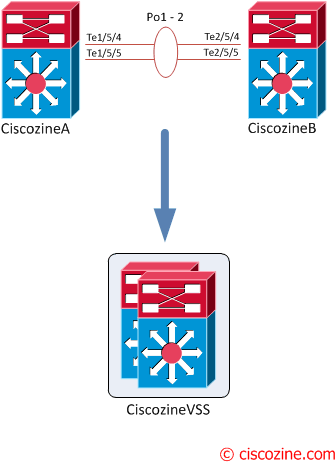
The Virtual Switching System is created by converting two standalone Catalyst 6500 systems to a Virtual Switching System. The conversion is a one-time process that requires a few simple configuration steps and a system reload. Once the individual chassis reload, they are converted into the Virtual Switching System.
All control plane functions are centrally managed by the active supervisor engine of the active virtual switch chassis, including:
The requirements to convert the 6500 into a Virtual Switching System are:
To convert two standalone chassis into a VSS, perform the following activities:
1. Configure each chassis as a VSS
Define a switch virtual domain ID to identify the VSS. The ID must be the same on each 6500; in this example the ID ‘100’ is used:
Configure the VSL port channel and member ports
The Virtual Switch Link (VSL), like the VPC peer-link in VPC, is clearly a vital part of the VSS. It provides the signaling path used for synchronizing the two supervisor engines’ control planes, as well as providing the data path for any user data traffic needing to pass between the two chassis.
Choose unique port-channel IDs for each chassis to form the VSL and configure them with the corresponding switch ID:
2. Convert to a VSS
Convert both switches to virtual switch mode. During these phases:
Wait more or less five minutes, then convert the second switch.
After the conversion, you will notice three things:
If needed, enable the standby console:
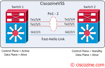
3. Configure the dual-active detection (optional)
The VSLs can be configured with up to eight links between the two switches across any combination of line cards or supervisor ports to provide a high level of redundancy. If for some rare reason all VSL connections are lost between the virtual switch members leaving each virtual switch assumes the role as the active virtual switch, and each virtual switch controls only its local ports. Duplication of this configuration can possibly have adverse effects to the network topology and traffic.
To avoid this disruptive scenario, Cisco has implemented different mechanisms to address this dual-active scenario:
In this tutorial, “fast-hello” is implemented.
Note: If the dual-active detection is not configured, the system will suggest to implement it!
4. Configure the switch priority (optional)
My suggestion is to statically define the switch priority (an higher-priority value assumes the active virtual switch role):
Changing the priority, a log message is generated:
After these steps, the VSS configuration is completed!
Multichassis EtherChannel
The multichassis EtherChannel (MEC) is another term to identify an etherchannel that allows a connected node to terminate the EtherChannel across the two physical Cisco Catalyst 6500 Series. In this example the “Ciscozine-L2” switch is connected to the CiscozineVSS using a MEC.
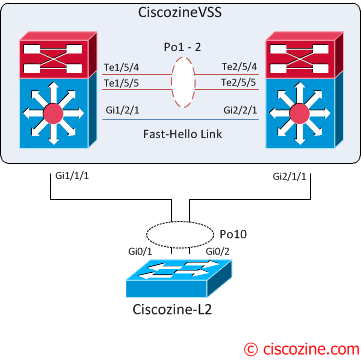
From the point of view of the Ciscozine-L2, the CiscozineVSS is a single device (like a stack):
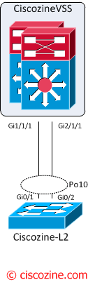
For these reasons, on the Ciscozine-L2 is possible define the port-channel10 with the interfaces Gi0/1 and Gi0/2. To find more informations about etherchannel read this article.
Useful show commands
To show basic VSS informations:
To find informations about fast-hello detection:
To identify the role/priority of the two switches:
To find more informations about the VSS status:
Note: After the VSS conversation, some “show” commands have the feature to view the output of individual switch! For instance, to see the modules of the second switch use “show module switch 2”.
Reload commands:
To reload a single unit:
where either Switch 1 or Switch 2 can be specified.
Vss cisco что такое
This chapter describes how to configure a virtual switching system (VSS) for the Catalyst 6500 series switch.

Note ![]() For complete syntax and usage information for the commands used in this chapter, see these publications:
For complete syntax and usage information for the commands used in this chapter, see these publications:
•![]() The Cisco IOS Virtual Switch Command Reference at this URL:
The Cisco IOS Virtual Switch Command Reference at this URL:
•![]() The Cisco IOS Release 12.2 publications at this URL:
The Cisco IOS Release 12.2 publications at this URL:
This chapter consists of these sections:
•![]() Understanding Virtual Switching Systems
Understanding Virtual Switching Systems
•![]() VSS Configuration Guidelines and Restrictions
VSS Configuration Guidelines and Restrictions
•![]() Configuring Virtual Switching Systems
Configuring Virtual Switching Systems
Understanding Virtual Switching Systems
These sections describe virtual switching systems:
•![]() Virtual Switching System Overview
Virtual Switching System Overview
•![]() Virtual Switching System Redundancy
Virtual Switching System Redundancy
•![]() Multichassis EtherChannels
Multichassis EtherChannels
•![]() Packet Handling
Packet Handling
•![]() System Monitoring
System Monitoring
•![]() Dual-Active Detection
Dual-Active Detection
•![]() Virtual Switching System Initialization
Virtual Switching System Initialization
Virtual Switching System Overview
Network operators increase network reliability by configuring switches in redundant pairs and by provisioning links to both switches in the redundant pair. Figure 4-1 shows a typical network configuration. Redundant network elements and redundant links can add complexity to network design and operation. Virtual switching simplifies the network by reducing the number of network elements and hiding the complexity of managing redundant switches and links.
A virtual switching system (VSS) combines a pair of Catalyst 6500 series switches into a single network element. The virtual switching system manages the redundant links, which externally act as a single port channel.
The virtual switching system simplifies network configuration and operation, by reducing the number of Layer 3 routing neighbors and by providing a loop-free Layer 2 topology.
Figure 4-1 Typical Network Design

The following sections present an overview of the VSS. These topics are covered in detail in subsequent chapters:
•![]() Key Concepts
Key Concepts
•![]() VSS Functionality
VSS Functionality
•![]() Hardware Requirements
Hardware Requirements
•![]() Understanding VSS Topology
Understanding VSS Topology
Key Concepts
The virtual switching system incorporates the following key concepts:
•![]() Virtual Switching System
Virtual Switching System
•![]() Active and Standby Chassis
Active and Standby Chassis
•![]() Virtual Switch Link
Virtual Switch Link
•![]() Multichassis EtherChannel
Multichassis EtherChannel
Virtual Switching System
A virtual switching system (VSS) combines a pair of switches into a single network element. For example, a VSS in the distribution layer of the network interacts with the access and core networks as if it were a single switch. See Figure 4-2.
An access switch connects to both chassis of the VSS using one logical port channel. The VSS manages redundancy and load balancing on the port channel. This capability enables a loop-free Layer 2 network topology. The virtual switching system also simplifies the Layer 3 network topology, because the VSS reduces the number of routing peers in the network.
Figure 4-2 Virtual Switching System in the Distribution Network

Active and Standby Chassis
When you create or restart a VSS, the peer chassis negotiate their roles. One chassis becomes the active chassis, and the other chassis becomes the standby.
The active chassis controls the VSS. It runs the Layer 2 and Layer 3 control protocols for the switching modules on both chassis. The active chassis also provides management functions for the VSS, such as line card online insertion and removal (OIR) and the console interface.
The active and standby chassis perform packet forwarding for ingress data traffic on their locally hosted interfaces. However, the standby chassis sends all control traffic to the active chassis for processing.
Virtual Switch Link
For the two chassis of the VSS to act as one network element, they need to share control information and data traffic.
The virtual switch link (VSL) is a special link that carries control and data traffic between the two chassis of a virtual switching system, as shown in Figure 4-3. VSL is implemented as an EtherChannel with up to eight links. VSL gives control traffic higher priority than data traffic so that control messages are never discarded. Data traffic is load balanced among the VSL links by the EtherChannel load-balancing algorithm.
Figure 4-3 Virtual Switch Link

Multichassis EtherChannel
An EtherChannel (also known as a port channel) is a collection of two or more physical links that combine to form one logical link. Layer 2 protocols operate on the EtherChannel as a single logical entity.
A multichassis EtherChannel (MEC) is a port channel that spans the two chassis of a virtual switching system. The access switch views the MEC as a standard port channel. See Figure 4-4.
The virtual switching system supports a maximum of 128 EtherChannels on one VSS. This limit applies to the combined total of regular EtherChannels and MECs. Because VSL requires two EtherChannel numbers (one for each chassis), there are 126 user-configurable EtherChannels.
Figure 4-4 Virtual Switching System with MEC

VSS Functionality
The following sections describe the main functionality of virtual switching systems:
•![]() Redundancy and High Availability
Redundancy and High Availability
•![]() Packet Handling
Packet Handling
•![]() System Management
System Management
•![]() Interface Naming Convention
Interface Naming Convention
•![]() Software Features
Software Features
Redundancy and High Availability
In a VSS, supervisor engine redundancy operates between the active and standby chassis. The peer chassis exchange configuration and state information across the VSL and the standby supervisor engine runs in hot standby mode.
The standby chassis monitors the active chassis using the VSL. If it detects failure, the standby chassis initiates a switchover and takes on the active role. When the failed chassis recovers, it takes on the standby role.
If the VSL fails completely, the standby chassis assumes that the active chassis has failed, and initiates a switchover. After the switchover, if both chassis are active, the dual-active detection feature detects this condition and initiates recovery action. For additional information about dual-active detection, see the «Dual-Active Detection» section.
Packet Handling
The active supervisor engine runs the Layer 2 and Layer 3 protocols and features for the virtual switching system (VSS) and manages the DFC line cards for both chassis.
The VSS uses VSL to communicate protocol and system information between the peer chassis and to carry data traffic between the chassis when required.
Both chassis perform packet forwarding for ingress traffic on their interfaces. If possible, ingress traffic is forwarded to an outgoing interface on the same chassis to minimize data traffic that must traverse the VSL.
Because the standby chassis is actively forwarding traffic, the active supervisor engine distributes updates to the standby supervisor engine PFC and all standby chassis DFCs.
System Management
The active supervisor engine acts as a single point of control for the virtual switching system. For example, the active supervisor engine handles OIR of switching modules on both chassis. The active supervisor engine uses VSL to send messages to and from local ports on the standby chassis.
The command console on the active supervisor engine is used to control both chassis. In virtual switch mode, the command console on the standby supervisor engine blocks attempts to enter configuration mode.
The standby chassis runs a subset of system management tasks. For example, the standby chassis handles its own power management.
Interface Naming Convention
In VSS mode, interfaces are specified using switch number (in addition to slot and port), because the same slot numbers are used on both chassis. For example, command interface 1/5/4 specifies port 4 of the switching module in slot 5 of switch 1. The command interface 2/5/4 specifies port 4 on the switching module in slot 5 of switch 2.
Software Features
With some exceptions, the virtual switching system has feature parity with standalone Catalyst 6500 series switch (12.2(33)SXH release). Major exceptions include:
•![]() The virtual switching system does not support MPLS or IPv6.
The virtual switching system does not support MPLS or IPv6.
•![]() The virtual switching system does not support supervisor engine redundancy within the chassis.
The virtual switching system does not support supervisor engine redundancy within the chassis.
Hardware Requirements
The following sections describe the hardware requirements of a virtual switching system:
•![]() Chassis and Modules
Chassis and Modules
•![]() VSL Hardware Requirements
VSL Hardware Requirements
•![]() PFC and DFC Requirements
PFC and DFC Requirements
•![]() Other Modules
Other Modules
Chassis and Modules
Table 4-1 describes the hardware requirements for the VSS chassis and modules.
Table 4-1 Virtual Switching System Hardware Requirements
The virtual switching system is available on chassis that supports VS-S720-10G supervisor engines and WS-X6708-10GE switching modules.
Note ![]() The two chassis do not need to be identical.
The two chassis do not need to be identical.
The virtual switching system requires Supervisor Engine 720 with 10-Gigabit Ethernet ports. You must use either two VS-S720-10G-3C or two VS-S720-10G-3CXL supervisor engine modules.
The two supervisor engines must match exactly.
The virtual switching system requires 67xx series switching modules.
The virtual switching system does not support classic, CEF256 or dCEF256 switching modules. In virtual switch mode, unsupported switching modules remain powered off.
VSL Hardware Requirements
The VSL EtherChannel supports only 10-Gigabit Ethernet ports. The 10-Gigabit Ethernet port can be located on the supervisor engine module or on a WS-X6708-10GE-3C or WS-X6708-10GE-3CXL switching module.
We recommend that you use both of the 10-Gigabit Ethernet ports on the supervisor engines to create the VSL between the two chassis.
You can add additional physical links to the VSL EtherChannel by using the 10-Gigabit Ethernet ports on WS-X6708-10GE switching modules.
PFC and DFC Requirements
The virtual switching system supports DFC3C or DFC3CXL hardware and does not support DFC3A/3B/3BXL hardware.
If any switching module in the VSS is provisioned with DFC3C, the whole VSS must operate in PFC3C mode. If a 67xx series switching module with a DFC3A/3B/3BXL is inserted in the chassis of a VSS, the module will remain unpowered, because VSS supports only DFC3C and DFC3CXL.
If the supervisor engines are provisioned with PFC3C, the VSS will automatically operate in 3C mode, even if some of the line cards are 3CXL. However, if the supervisor engines are provisioned with PFC3CXL, but some of the line cards are 3C, you need to configure the virtual switching system to operate in 3C mode. The platform hardware vsl pfc mode pfc3c configuration command sets the system to operate in 3C mode after the next restart. See the «SSO Dependencies» section for further details about this command.
Other Modules
Only the NAM service modules are supported (WS-SVC-NAM-1 and WS-SVC-NAM-2).
No WAN modules are currently supported in virtual switch mode.
Understanding VSS Topology
A virtual switching system (VSS) contains two chassis that communicate using the virtual switch link (VSL). VSL is a special port group.
We recommend that you configure both of the 10-Gigabit Ethernet ports on the supervisor engines as VSL ports. Optionally, you can also configure the VSL port group to contain switching module 10-Gigabit Ethernet ports. This configuration provides additional VSL capacity. See Figure 4-5 for an example topology.
Figure 4-5 VSL Topology Example

Virtual Switching System Redundancy
The following sections describe how redundancy in a virtual switching system supports network high availability:
•![]() Overview
Overview
•![]() RPR and SSO Redundancy
RPR and SSO Redundancy
•![]() Failed Chassis Recovery
Failed Chassis Recovery
•![]() VSL Failure
VSL Failure
•![]() User Actions
User Actions
Overview
A virtual switching system (VSS) operates stateful switchover (SSO) between the active and standby supervisor engines. Compared to standalone mode, a virtual switching system has the following important differences in its redundancy model:
•![]() The active and standby supervisor engines are hosted in separate chassis and use virtual switch link (VSL) to exchange information.
The active and standby supervisor engines are hosted in separate chassis and use virtual switch link (VSL) to exchange information.
•![]() The active supervisor engine controls both chassis of the VSS. The active supervisor engine runs the Layer 2 and Layer 3 control protocols and manages the line cards on both chassis.
The active supervisor engine controls both chassis of the VSS. The active supervisor engine runs the Layer 2 and Layer 3 control protocols and manages the line cards on both chassis.
•![]() The active and standby chassis both perform data traffic forwarding.
The active and standby chassis both perform data traffic forwarding.
If the active supervisor engine fails, the standby supervisor engine initiates a switchover and assumes the active role.
RPR and SSO Redundancy
A virtual switching system operates with stateful switchover (SSO) redundancy if it meets the following requirements:
•![]() Both supervisor engines must be running the same software version.
Both supervisor engines must be running the same software version.
•![]() VSL-related configuration in the two chassis must match.
VSL-related configuration in the two chassis must match.
•![]() PFC mode must match.
PFC mode must match.
See the «SSO Dependencies» section for additional details about the requirements for SSO redundancy on a virtual switching system.
With SSO redundancy, the standby supervisor engine is always ready to assume control following a fault on the active supervisor engine. Configuration, forwarding, and state information is synchronized from the active supervisor engine to the redundant supervisor engine at startup and whenever changes to the active supervisor engine configuration occur. If a switchover occurs, traffic disruption is minimized.
If a virtual switching system does not meet the requirements for SSO redundancy, the VSS will use route processor redundancy (RPR). With RPR redundancy, the active supervisor engine does not synchronize configuration changes or state information with the standby. The standby supervisor engine is only partially initialized and the switching modules on the standby supervisor are not powered up. If a switchover occurs, the standby supervisor engine completes its initialization and powers up the switching modules. Traffic is disrupted for approximately 2 minutes.
The VSS normally runs stateful switchover (SSO) between the active and standby supervisor engines (see Figure 4-6). The VSS determines the role of each supervisor engine during initialization.
The supervisor engine in the standby chassis runs in hot standby state. The virtual switching system uses the VSL link to synchronize configuration data from the active to the standby supervisor engine. Also, protocols and features that support high availability synchronize their events and state information to the standby supervisor engine.
Figure 4-6 Chassis Roles in a VSS
Failed Chassis Recovery
If the active chassis or supervisor engine fails, the VSS initiates a stateful switchover (SSO) and the former standby supervisor engine assumes the active role. The failed chassis performs recovery action by reloading the supervisor engine.
If the standby chassis or supervisor engine fails, no switchover is required. The failed chassis performs recovery action by reloading the supervisor engine.
The VSL links are unavailable while the failed chassis recovers. After the chassis reloads, it becomes the new standby chassis and the virtual switching system reinitializes the VSL links between the two chassis.
Note ![]() If preemption is enabled and the new standby chassis is higher priority than the active chassis, the VSS performs a second switchover so that the higher priority chassis is active. For information about configuring priority and preemption, see the «Configuring VSL Switch Priority» section.
If preemption is enabled and the new standby chassis is higher priority than the active chassis, the VSS performs a second switchover so that the higher priority chassis is active. For information about configuring priority and preemption, see the «Configuring VSL Switch Priority» section.
The switching modules on the failed chassis are unavailable during recovery, so the VSS operates only with the MEC links that terminate on the active chassis. The bandwidth of the VSS is reduced until the failed chassis has completed its recovery and become operational again. Any devices that are connected only to the failed chassis experience an outage.
Note ![]() The VSS may experience a brief data path disruption when the switching modules in the standby chassis become operational after the SSO.
The VSS may experience a brief data path disruption when the switching modules in the standby chassis become operational after the SSO.
VSL Failure
In virtual switch mode, fast link notification is enabled on all port channel members (including VSL ports) to ensure fast recovery from VSL failures.
Note ![]() Fast link notification is not compatible with link debounce mechanisms. In virtual switch mode, link debounce is disabled on all port channel members.
Fast link notification is not compatible with link debounce mechanisms. In virtual switch mode, link debounce is disabled on all port channel members.
If a single VSL physical link goes down, the VSS adjusts the port group so that the failed link is not selected.
If the standby chassis detects complete VSL link failure, it initiates a stateful switchover (SSO). If the active chassis has failed (causing the VSL links to go down), the scenario is chassis failure, as described in the previous section.
If only the VSL has failed and the active chassis is still operational, this is a dual-active scenario. The VSS detects that both chassis are operating in active mode and performs recovery action. See the «Dual-Active Detection» section for additional details about dual-active scenario.
User Actions
From the active chassis command console, users can initiate a VSS switchover or a reload.
If you enter the reload command from the command console, the entire virtual switching system performs a reload.
To reload only the standby chassis, use redundancy reload peer command.
To force a switchover from the active to the standby supervisor engine, use the redundancy force-switchover command.
Multichassis EtherChannels
Multichassis EtherChannel (MEC) is an EtherChannel with ports that terminate on both chassis of the VSS. These sections describe multichassis EtherChannels:
•![]() Overview
Overview
•![]() Failure Scenarios
Failure Scenarios
Overview
Multichassis EtherChannel (MEC) is an EtherChannel with ports that terminate on both chassis of the VSS (see Figure 4-7). A VSS MEC can connect to any network element that supports EtherChannel (such as a host, server, router, or switch).
At the VSS, a MEC is an EtherChannel with additional capability: the VSS balances the load across ports in each chassis independently. For example, if traffic enters the active chassis, the VSS will select a MEC link from the active chassis. This MEC capability ensures that data traffic does not unnecessarily traverse the VSL.
Each MEC can optionally be configured to support either PAgP or LACP. These protocols run only on the active chassis. PAgP or LACP control packets destined for a MEC link on the standby chassis are sent across VSL.
Figure 4-7 MEC Topology Example

A MEC can support up to eight active physical links, which can be distributed in any way between the active and standby chassis.
Failure Scenarios
We recommend that you configure the MEC with at least one link to each chassis. This configuration conserves VSL bandwidth (traffic egress link is on the same chassis as the ingress link), and increases network reliability (if one VSS supervisor engine fails, the MEC is still operational).
The following sections describe possible failures and the resulting impacts:
•![]() Single MEC Link Failure
Single MEC Link Failure
•![]() All Links to the Active Chassis Fail
All Links to the Active Chassis Fail
•![]() All Links to the Standby Chassis Fail
All Links to the Standby Chassis Fail
•![]() All Links Fail
All Links Fail
•![]() Standby Chassis Failure
Standby Chassis Failure
•![]() Active Chassis Failure
Active Chassis Failure
Single MEC Link Failure
If a link within the MEC fails (and other links in the MEC are still operational), the MEC redistributes the load among the operational links, as in a regular port.
All Links to the Active Chassis Fail
If all links to the active chassis fail, the MEC becomes a regular EtherChannel with operational links to the standby chassis.
Data traffic terminating on the active chassis reaches the MEC by crossing the VSL to the standby chassis. Control protocols continue to run in the active chassis. Protocol messages reach the MEC by crossing the VSL.
All Links to the Standby Chassis Fail
If all links fail to the standby chassis, the MEC becomes a regular EtherChannel with operational links to active chassis.
Control protocols continue to run in the active chassis. All control and data path traffic from the standby chassis reaches the MEC by crossing the VSL to the active chassis.
All Links Fail
If all links in a MEC fail, the logical interface for the EtherChannel is set to unavailable. Layer 2 control protocols perform the same corrective action as for a a link-down event on a regular EtherChannel.
On adjacent switches, routing protocols and Spanning Tree Protocol (STP) perform the same corrective action as for a regular EtherChannel.
Standby Chassis Failure
If the standby chassis fails, the MEC becomes a regular EtherChannel with operational links on the active chassis.
The connected switches detect the link failures, and adjust their load-balancing algorithms to use only the links to the active chassis.
Active Chassis Failure
Active chassis failure results in a stateful switchover (SSO). See the «Virtual Switching System Redundancy» section for details about SSO on a virtual switching system. After the switchover, the MEC is operational on the new active chassis. Connected switches detect the link failures (to the failed chassis), and adjust their load-balancing algorithms to use only the links to the new active chassis.
Figure 4-8 MEC Configuration Example
Packet Handling
In a virtual switching system (VSS), the active supervisor engine runs the Layer 2 and Layer 3 protocols and features for the VSS and manages the DFC line cards for both chassis.
The virtual switching system uses VSL to communicate system and protocol information between the peer chassis and to carry data traffic between the two chassis.
Both chassis perform packet forwarding for ingress traffic on their local interfaces. The virtual switching system minimizes the amount of data traffic that must traverse the VSL.
The following sections describe packet handling in a virtual switching system:
•![]() Traffic on VSL
Traffic on VSL
•![]() Layer 2 Protocols
Layer 2 Protocols
•![]() Layer 3 Protocols
Layer 3 Protocols
•![]() SPAN
SPAN
Traffic on VSL
The VSL carries data traffic and in-band control traffic between the two chassis. All frames forwarded over the VSL link are encapsulated with a special 32-byte header, which provides information for the VSS to forward the packet on the peer chassis.
VSL transports control messages between the two chassis. Messages include protocol messages that are processed by the active supervisor engine, but received or transmitted by interfaces on the standby chassis. Control traffic also includes line card programming between the active supervisor engine and line cards on the standby chassis.
The VSS needs to transmit data traffic over VSL under the following circumstances:
•![]() Layer 2 traffic flooded over a VLAN (even for dual-homed links).
Layer 2 traffic flooded over a VLAN (even for dual-homed links).
•![]() Packets processed by software on the active supervisor engine where the ingress interface is on the standby chassis.
Packets processed by software on the active supervisor engine where the ingress interface is on the standby chassis.
•![]() The packet destination is on the peer chassis, such as the following examples:
The packet destination is on the peer chassis, such as the following examples:
–![]() Traffic within a VLAN where the known destination interface is on the peer chassis.
Traffic within a VLAN where the known destination interface is on the peer chassis.
–![]() Traffic that is replicated for a multicast group and the multicast receivers are on the peer chassis.
Traffic that is replicated for a multicast group and the multicast receivers are on the peer chassis.
–![]() The known unicast destination MAC address is on the peer chassis.
The known unicast destination MAC address is on the peer chassis.
–![]() The packet is a MAC notification frame destined for a port on the peer chassis.
The packet is a MAC notification frame destined for a port on the peer chassis.
VSL also transports system data, such as NetFlow export data and SNMP data, from the standby chassis to the active supervisor engine.
To preserve the VSL bandwidth for critical functions, the VSS uses strategies to minimize user data traffic that must traverse the VSL. For example, if an access switch is dual-homed (attached with a MEC terminating on both VSS chassis), the VSS transmits packets to the access switch using a link on the same chassis as the ingress link.
Traffic on the VSL is load-balanced with the same global hashing algorithms available for EtherChannels (the default algorithm is source-destination IP).
Layer 2 Protocols
The active supervisor engine runs the Layer 2 protocols (such as STP and VTP) for the line cards on both chassis. Protocol messages that are transmitted and received on the standby chassis line cards must traverse VSL to reach the active supervisor engine.
The following sections describe Layer 2 protocols for a virtual switching system:
•![]() Spanning Tree Protocol
Spanning Tree Protocol
•![]() Virtual Trunk Protocol
Virtual Trunk Protocol
•![]() EtherChannel Control Protocols
EtherChannel Control Protocols
Spanning Tree Protocol
The active chassis runs Spanning Tree Protocol (STP). The standby chassis redirects STP BPDUs across the VSL to the active chassis.
The STP bridge ID is commonly derived from the chassis MAC address. To ensure that the bridge ID does not change after a switchover, the virtual switching system continues to use the original chassis MAC address for the STP Bridge ID.
Virtual Trunk Protocol
Virtual Trunk Protocol (VTP) uses the IP address of the switch and local current time for version control in advertisements. After a switchover, VTP uses the IP address of the newly active chassis.
EtherChannel Control Protocols
Link Aggregation Control Protocol (LACP) and Port Aggregation Protocol (PAgP) packets contain a device identifier. The virtual switching system defines a common device identifier for both chassis to use.
A new PAgP enhancement has been defined for assisting with dual-active scenario detection. For additional information, see the «Dual-Active Detection» section.
Layer 3 Protocols
The MSFC on the active supervisor engine runs the Layer 3 protocols and features for the VSS. Both chassis perform packet forwarding for ingress traffic on their interfaces. If possible, ingress traffic is forwarded to an outgoing interface on the same chassis, to minimize data traffic that must traverse the VSL.
Because the standby chassis is actively forwarding traffic, the active supervisor engine distributes updates to the standby supervisor engine PFC and all standby chassis DFCs.
The following sections describe Layer 3 protocols for a virtual switching system:
•![]() IPv4
IPv4
•![]() IPv6 and MPLS
IPv6 and MPLS
•![]() IPv4 Multicast
IPv4 Multicast
•![]() Software Features
Software Features
The supervisor engine on the active chassis runs the IPv4 routing protocols and performs any required software forwarding.
Routing updates received on the standby chassis are redirected to the active chassis across VSL.
Hardware forwarding is distributed across all DFCs on the VSS. The supervisor engine on the active chassis sends FIB updates to all local DFCs, remote DFCs, and the standby supervisor engine PFC.
All hardware routing uses the router MAC address assigned by the active supervisor engine. After a switchover, the original MAC address is still used.
The supervisor engine on the active chassis performs all software forwarding (for protocols such as IPX) and feature processing (such as fragmentation and TTL exceed). If a switchover occurs, software forwarding is disrupted until the new active supervisor engine obtains the latest CEF and other forwarding information.
In virtual switch mode, the requirements to support non-stop forwarding (NSF) are the same as in standalone mode. For additional information about NSF requirements, refer to the Catalyst 6500 Series Switch Cisco IOS Configuration Guide, Release 12.2SX.
From a routing peer perspective, EtherChannels remain operational during a switchover (only the links to the failed chassis are down, so the routing adjacencies remains valid).
The virtual switching system implements path filtering by storing only local paths (paths that do not traverse the VSL) in the FIB entries. Therefore, IP forwarding performs load sharing among the local paths. If no local paths to a given destination are available, the VSS updates the FIB entry to include remote paths (reachable by traversing the VSL).
IPv6 and MPLS
The virtual switching system does not support IPv6 or MPLS.
IPv4 Multicast
The IPv4 multicast protocols run on the active supervisor engine. Internet Group Management Protocol (IGMP) and Protocol Independent Multicast (PIM) protocol packets received on the standby supervisor engine are transmitted across VSL to the active chassis.
The active supervisor engine sends IGMP and PIM protocol packets to the standby supervisor engine in order to maintain Layer 2 information for stateful switchover (SSO).
The active supervisor engine distributes multicast FIB and adjacency table updates to the standby supervisor and line card DFCs.
The virtual switching system does not support SSO for Layer 3 multicast. Multicast routes are programmed in the hardware in the standby supervisor engine, using nodal NSF updates.
In virtual switch mode, the active chassis does not program the multicast expansion table (MET) on the standby chassis. The standby supervisor engine programs the outgoing interface hardware entries for all local multicast receivers
If all line cards on the active chassis and standby chassis are egress capable, the multicast replication mode is set to egress mode; otherwise, the mode is set to ingress mode.
In egress mode, replication is distributed to DFCs that have ports in outgoing VLAN for a particular flow. In ingress mode, replication for all outgoing VLANs is done on the ingress DFC.
For packets traversing VSL, all Layer 3 multicast replication occurs on the ingress chassis. If there are multiple receivers on the egress chassis, replicated packets are forwarded over the VSL.
Software Features
Software features run only on the active supervisor engine. Incoming packets to the standby chassis that require software processing are sent across the VSL.
For features supported in hardware, the ACL configuration is sent to the TCAM manager on the active supervisor engine, the standby supervisor engine, and all DFCs.
The virtual switching system supports all SPAN features for non-VSL interfaces. The virtual switching system supports SPAN features on VSL interfaces with the following limitations:
•![]() If the VSL is configured as a local SPAN source, the SPAN destination interface must be on the same chassis as the source interface.
If the VSL is configured as a local SPAN source, the SPAN destination interface must be on the same chassis as the source interface.
•![]() VSL cannot be configured as a SPAN destination.
VSL cannot be configured as a SPAN destination.
•![]() VSL cannot be configured as a traffic source of RSPAN, ERSPAN, or egress-only SPAN.
VSL cannot be configured as a traffic source of RSPAN, ERSPAN, or egress-only SPAN.
The number of SPAN sessions available to a VSS is the same as for a single chassis running in standalone mode.
System Monitoring
The following sections describe system monitoring and system management for a virtual switching system:
•![]() Power Management
Power Management
•![]() Environmental Monitoring
Environmental Monitoring
•![]() File System Access
File System Access
•![]() Diagnostics
Diagnostics
•![]() Service Modules
Service Modules
•![]() Network Management
Network Management
Power Management
From the active chassis, you can control power-related functions for the standby chassis. For example, use the (no) power enable switch command to control power to the modules and slots on the standby chassis. Use the show power switch command to see the current power settings and status.
Environmental Monitoring
Environmental monitoring runs on both supervisor engines. The standby chassis reports notifications to the active supervisor engine. The active chassis gathers log messages for both chassis. The active chassis synchronizes the calendar and system clock to the standby chassis.
File System Access
You can access file systems of both chassis from the active chassis. Prefix the device name with the switch number and slot number to access directories on the standby chassis. For example, the command dir sw2_slot5disk0 lists the contents of disk0 on the standby chassis (assuming switch 2 is the standby chassis). You can access the standby chassis file system only when VSL is operational.
Diagnostics
You can use the diagnostic schedule and diagnostic start commands on a VSS. In virtual switch mode, these commands require an additional parameter, which specifies the chassis to apply the command.
When you configure a VSL port on a switching module or a supervisor engine module, the diagnostics suite incorporates additional tests for the VSL ports.
Use the show diagnostic content command to display the diagnostics test suite for a module.
VSL Diagnostics
The following VSL-specific diagnostics tests are available on WS-X6708-10GE switching modules with VSL ports. These tests are disruptive:
•![]() TestVslBridgeLink
TestVslBridgeLink
•![]() TestVslLocalLoopback
TestVslLocalLoopback
The following VSL-specific diagnostics tests are available on a Supervisor Engine 720-10GE with VSL ports. These tests are disruptive:
•![]() TestVSActiveToStandbyLoopback
TestVSActiveToStandbyLoopback
•![]() TestVslBridgeLink
TestVslBridgeLink
•![]() TestVslLocalLoopback
TestVslLocalLoopback
The following VSL-specific diagnostics test is available for VSL ports on the switching module or the supervisor engine. This test is not disruptive:
•![]() TestVslStatus
TestVslStatus
Service Modules
The only service module supported by the virtual switching system is the network analysis module (WS-SVC-NAM-1 and WS-SVC-NAM-2).
The supervisor engine in the same chassis as the NAM controls the powering up of the NAM. After the NAM is online, you initiate a session from the active supervisor engine to configure and maintain the NAM.
The active chassis performs the graceful shutdown of the NAM module, even if the NAM module is in the standby chassis.
Use the Session command to connect to the NAM. If NAM is on the standby chassis, the session runs over the VSL.
Network Management
The following sections describe network management for a virtual switching system:
•![]() Telnet over SSH Sessions and the Web Browser User Interface
Telnet over SSH Sessions and the Web Browser User Interface
•![]() SNMP
SNMP
•![]() Command Console
Command Console
Telnet over SSH Sessions and the Web Browser User Interface
A virtual switching system supports remote access using Telnet over SSH sessions and the Cisco web browser user interface.
All remote access is directed to the active supervisor engine, which manages the whole VSS.
If the virtual switching system performs a switchover, Telnet over SSH sessions and web browser sessions are disconnected.
The SNMP agent runs on the active supervisor engine.
CISCO-VIRTUAL-SWITCH-MIB is a new MIB for virtual switch mode and contains the following main components:
Command Console
You need to cable physical console connections to both supervisor engine console ports. You can only use configuration mode in the console for the active supervisor engine.
The console on the standby chassis will indicate that chassis is operating in standby mode by adding the characters «-stdby» to the command line prompt. You cannot enter configuration mode on the standby chassis console.
The following example shows the prompt on the standby console:
Router-stdby> show switch virtual
Dual-Active Detection
If the VSL fails, the standby chassis cannot determine the state of the active chassis. To ensure that switchover occurs without delay, the standby chassis assumes the active chassis has failed and initiates switchover to take over the active role.
If the original active chassis is still operational, both chassis are now active. This situation is called dual-active scenario. Dual-active scenario can have adverse affects on network stability, because both chassis use the same IP addresses, SSH keys, and STP bridge ID. The virtual switching system (VSS) must detect dual-active scenario and take recovery action.
The virtual switching system supports two methods for detecting dual-active scenario. One method uses enhanced PAgP messaging over the MEC links to communicate between the two chassis. The other method uses IP BFD messaging over a backup Ethernet connection.
You can configure both detection methods to be active at the same time. The PAgP method takes priority, because it detects dual-active scenario much more quickly than the IP BFD method.
The two methods are described in the following sections:
•![]() Dual-Active Detection Using Enhanced PAgP
Dual-Active Detection Using Enhanced PAgP
•![]() Dual-Active Detection Using IP BFD
Dual-Active Detection Using IP BFD
•![]() Recovery Actions
Recovery Actions
Dual-Active Detection Using Enhanced PAgP
Port aggregation protocol (PAgP) is a Cisco-proprietary protocol for managing EtherChannels. If a VSS MEC terminates to a Cisco switch, you can run PAgP protocol on the MEC.
If PAgP is running on the MECs between the VSS and an upstream or downstream switch, the VSS can use PAgP to detect dual-active scenario. The MEC must have at least one port on each chassis of the VSS.
In virtual switch mode, PAgP messages include a new TLV which contains the ID of the active switch. Only switches in virtual switch mode send the new TLV.
For dual-active detection to operate successfully, one or more of the connected switches needs to be able to process the new TLV. Catalyst 6500 series switches with Supervisor Engine 32 and Supervisor Engine 720 have this capability, if they are running Cisco IOS software release12.2(33)SXH or later. For a list of other Cisco products that support enhanced PAgP, refer to Release Notes for Cisco IOS Release 12.2(33)SXH and Later Releases.
When the standby chassis detects VSL failure, it initiates SSO and becomes active. Subsequent PAgP messages to the connected switch from the newly active chassis contain the new active ID. The connected switch send PAgP messages with the new active ID to both of the VSS chassis.
If the formerly active chassis is still operational, it detects the dual-active scenario because the active ID in the PAgP messages changes. This chassis initiates recovery actions as described in the «Recovery Actions» section.
Dual-Active Detection Using IP BFD
To use the IP BFD detection method, you must provision a direct Ethernet connection between the two switches. Regular Layer 3 ping will not function correctly on this connection, as both chassis have the same IP address. The virtual switching system instead uses the Bidirectional Forwarding Detection (BFD) protocol.
If the VSL goes down, both chassis create BFD neighbors, and try to establish adjacency. If the original active chassis receives an adjacency message, it realizes that this is dual-active scenario, and initiates recovery.
Note ![]() If FlexLinks are configured on the VSS, we recommend using the PAgP detection method. Do not configure FlexLinks and BFD dual-active detection on the same VSS.
If FlexLinks are configured on the VSS, we recommend using the PAgP detection method. Do not configure FlexLinks and BFD dual-active detection on the same VSS.
Recovery Actions
The chassis shuts down all of its non-VSL interfaces (except interfaces configured to be excluded from shutdown) to remove itself from the network, and waits in recovery mode until the VSL links have recovered. User intervention may be required to fix the VSL failure. When both chassis detect that VSL is operational again, the previously active chassis reloads and comes into service as the standby chassis.
Virtual Switching System Initialization
A virtual switching system (VSS) is formed when the two chassis and the VSL link between them become operational. The peer chassis communicate over the VSL to negotiate the chassis roles.
If only one chassis becomes operational, it assumes the active role. The VSS forms when the second chassis becomes operational and both chassis bring up their VSL interfaces.
Virtual switching system initialization is described in the following sections:
•![]() Virtual Switch Link Protocol
Virtual Switch Link Protocol
•![]() SSO Dependencies
SSO Dependencies
•![]() Initialization Procedure
Initialization Procedure
Virtual Switch Link Protocol
The Virtual Switch Link Protocol (VSLP) consists of several protocols that contribute to virtual switch initialization. The VSLP includes the following protocols:
•![]() Role Resolution Protocol
Role Resolution Protocol
The peer chassis use Role Resolution Protocol (RRP) to negotiate the role (active or standby) for each chassis.
•![]() Link Management Protocol
Link Management Protocol
The Link Management Protocol (LMP) runs on all VSL links, and exchanges information required to establish communication between the two chassis.
LMP identifies and rejects any unidirectional links. If LMP flags a unidirectional link, the chassis that detects the condition brings the link down and up to restart the VSLP negotiation. VSL moves the control traffic to another port if necessary.
SSO Dependencies
For the VSS to operate with SSO redundancy, the VSS must meet the following conditions:
• ![]() Identical software versions
Identical software versions
Both supervisor engine modules on the VSS must be running the identical software version.
•![]() VSL configuration consistency
VSL configuration consistency
During the startup sequence, the standby chassis sends virtual switch information from the startup-config file to the active chassis.
The active chassis ensures that the following information matches correctly on both chassis:
–![]() Switch virtual domain
Switch virtual domain
–![]() Switch virtual node
Switch virtual node
–![]() Switch priority
Switch priority
–![]() Switch preempt
Switch preempt
–![]() VSL port channel: switch virtual link identifier
VSL port channel: switch virtual link identifier
–![]() VSL ports: channel-group number, shutdown, total number of VSL ports
VSL ports: channel-group number, shutdown, total number of VSL ports
–![]() Power redundancy-mode
Power redundancy-mode
–![]() Power enable on VSL modules
Power enable on VSL modules
If the VSS detects a mismatch, it prints out an error message on the active chassis console and the standby chassis comes up in RPR mode.
After you correct the configuration file, save the file by entering the copy running-config startup-config command on the active chassis, and then restart the standby chassis.
•![]() PFC mode check
PFC mode check
If both supervisor engines are provisioned with PFC3C, the VSS will automatically operate in PFC3C mode, even if some of the switching modules are equipped with 3CXL daughter feature cards (DFCs).
However, if the supervisor engines are provisioned with PFC3CXL and there is a mixture of DFC3C and DFC3CXL switching modules, the system PFC mode will depend on how the 3C and 3CXL switching modules are distributed between the two chassis.
Each chassis in the VSS determines its system PFC mode. If the supervisor engine of a given chassis is provisioned with PFC3CXL and all the switching modules in the chassis are provisioned with DFC3CXL, the PFC mode for the chassis is PFC3CXL. However, if any of the switching modules is provisioned with DFC3C, the chassis PFC mode will be set to PFC3C. If there is a mismatch between the PFC modes of two chassis, the VSS will come up in RPR mode instead of SSO mode. You can prevent this situation by using the platform hardware vsl pfc mode pfc3c command to force the VSS to operate in PFC3C mode after the next reload.
If these conditions are not met, the VSS operates in RPR redundancy mode. For a description of SSO and RPR, see the «Virtual Switching System Redundancy» section.
Initialization Procedure
The following sections describe the VSS initialization procedure:
•![]() VSL Initialization
VSL Initialization
•![]() System Initialization
System Initialization
•![]() VSL Down
VSL Down
VSL Initialization
A VSS is formed when the two chassis and the VSL link between them become operational. Because both chassis need to be assigned their role (active or standby) before completing initialization, VSL is brought online before the rest of the system is initialized. The initialization sequence is as follows:
1. ![]() The virtual switching system initializes all cards with VSL ports, and then initializes the VSL ports.
The virtual switching system initializes all cards with VSL ports, and then initializes the VSL ports.
2. ![]() The two chassis communicate over VSL to negotiate their roles (active or standby).
The two chassis communicate over VSL to negotiate their roles (active or standby).
3. ![]() The active chassis completes the boot sequence, including the consistency check described in the «SSO Dependencies» section.
The active chassis completes the boot sequence, including the consistency check described in the «SSO Dependencies» section.
4. ![]() If the consistency check completed successfully, the standby chassis comes up in SSO standby mode. If the consistency check failed, the standby chassis comes up in RPR mode.
If the consistency check completed successfully, the standby chassis comes up in SSO standby mode. If the consistency check failed, the standby chassis comes up in RPR mode.
5. ![]() The active chassis synchronizes configuration and application data to the standby chassis.
The active chassis synchronizes configuration and application data to the standby chassis.
System Initialization
If you boot both chassis simultaneously, the VSL ports become active, and the chassis will come up as active and standby. If priory is configured, the higher priority switch becomes active.
If you boot up only one chassis, the VSL ports remain inactive, and the chassis comes up as active. When you subsequently boot up the other chassis, the VSL links become active, and the new chassis comes up as standby. If you have configured preemption and the new chassis has the higher priority, it will initiate a switchover to become the active switch. The formerly active chassis reloads and comes up as standby.
VSL Down
If the virtual switch link (VSL) is down when both chassis try to boot up, the situation is similar to a dual-active scenario.
One of the chassis becomes active and the other chassis initiates recovery from dual-active scenario. For further information, see the «Configuring Dual-Active Detection» section.
VSS Configuration Guidelines and Restrictions
When configuring the VSS, note the following guidelines and restrictions:
•![]() The virtual switching system configurations in the startup-config file must match on both chassis.
The virtual switching system configurations in the startup-config file must match on both chassis.
•![]() If you configure new values for switch priority or preemption, the change only takes effect after you save the configuration file and perform a restart.
If you configure new values for switch priority or preemption, the change only takes effect after you save the configuration file and perform a restart.
When configuring MECs, note the following guidelines and restrictions:
•![]() All links in a MEC must terminate locally on the active or standby chassis of the same virtual domain.
All links in a MEC must terminate locally on the active or standby chassis of the same virtual domain.
•![]() For a MEC using LACP control protocol, minlinks defines the minimum number of physical links in each chassis for the MEC to be operational.
For a MEC using LACP control protocol, minlinks defines the minimum number of physical links in each chassis for the MEC to be operational.
•![]() For a MEC using LACP control protocol, maxbundle defines the maximum number of links in the MEC across the whole VSS.
For a MEC using LACP control protocol, maxbundle defines the maximum number of links in the MEC across the whole VSS.
•![]() MEC supports LACP 1:1 redundancy. For additional information about LACP 1:1 redundancy, refer to the «Configuring LACP 1:1 Redundancy» section.
MEC supports LACP 1:1 redundancy. For additional information about LACP 1:1 redundancy, refer to the «Configuring LACP 1:1 Redundancy» section.
•![]() A MEC can be connected to another MEC on a different virtual switching system domain.
A MEC can be connected to another MEC on a different virtual switching system domain.
When configuring dual-active detection, note the following guidelines and restrictions:
•![]() If FlexLinks are configured on the VSS, we recommend using the PAgP detection method. Do not configure FlexLinks and BFD dual-active detection on the same VSS.
If FlexLinks are configured on the VSS, we recommend using the PAgP detection method. Do not configure FlexLinks and BFD dual-active detection on the same VSS.
Configuring Virtual Switching Systems
These sections describe how to configure virtual switching systems:
•![]() Converting to a Virtual Switching System
Converting to a Virtual Switching System
•![]() Displaying Virtual Switching System Information
Displaying Virtual Switching System Information
•![]() Converting a Virtual Switching System to Standalone Chassis
Converting a Virtual Switching System to Standalone Chassis
•![]() Configuring Virtual Switching System Parameters
Configuring Virtual Switching System Parameters
•![]() Configuring Multichannel EtherChannels
Configuring Multichannel EtherChannels
•![]() Configuring Dual-Active Detection
Configuring Dual-Active Detection
Converting to a Virtual Switching System
By default, the Catalyst 6500 series switch is configured to operate in standalone mode (the switch is a single chassis). The virtual switching system combines two standalone switches into one virtual switching system (VSS), operating in virtual switch mode.
To convert two standalone chassis into a VSS, you perform the following major activities:
•![]() Save the standalone configuration files.
Save the standalone configuration files.
•![]() Configure each chassis as a VSS.
Configure each chassis as a VSS.
•![]() Convert to virtual switching system.
Convert to virtual switching system.
•![]() Configure the peer VSL information.
Configure the peer VSL information.
In virtual switch mode, both chassis use the same configuration file. When you make configuration changes on the active chassis, these changes are automatically propagated to the standby chassis.
The tasks required to convert the standalone chassis to a VSS are detailed in the following sections:
•![]() Backing Up the Standalone Configuration
Backing Up the Standalone Configuration
•![]() Assigning Virtual Switch Domain and Switch Numbers
Assigning Virtual Switch Domain and Switch Numbers
•![]() Configuring VSL Port Channel and Ports
Configuring VSL Port Channel and Ports
•![]() Converting the Chassis to Virtual Switch Mode
Converting the Chassis to Virtual Switch Mode
•![]() Auto-Configuring the Standby VSL Information
Auto-Configuring the Standby VSL Information
•![]() (Optional) Configuring Standby Chassis Modules
(Optional) Configuring Standby Chassis Modules
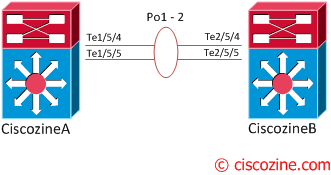
In the procedures that follow, the example commands assume the configuration shown in Figure 4-9.
Figure 4-9 Example VSS

Two chassis, A and B, are converted into a VSS with virtual switch domain 100. Interface 10-Gigabit Ethernet 5/1 on Switch 1 is connected to interface10-Gigabit Ethernet 5/2 on Switch 2 to form the VSL.
Backing Up the Standalone Configuration
Save the configuration files for both chassis operating in standalone mode. You need these files to revert to standalone mode from virtual switch mode. On Switch 1, perform this task:
Switch-1# copy running-config startup-config
(Optional) Saves the running configuration to startup configuration.
Switch-1# copy startup-config disk0:old-startup-config
Copies the startup configuration to a backup file.
Perform the following task on Switch 2:
Switch-2# copy running-config startup-config
(Optional) Save the running configuration to the startup configuration file.
Switch-2# copy startup-config disk0:old-startup-config
Copy the startup configuration to a backup file.
Assigning Virtual Switch Domain and Switch Numbers
You must configure the same virtual switch domain number on both chassis of the VSS. The virtual switch domain is a number between 1 and 255, and must be unique for each VSS in your network (the domain number is incorporated into various identifiers to ensure that these identifiers are unique across the network).
Within the VSS, you must configure a unique switch number for each chassis.
To configure the virtual switch domain and switch number on both chassis, perform this task on Switch 1:
Switch-1(config)# switch virtual domain 100
Configures the virtual switch domain on Chassis A.
Switch-1(config-vs-domain)# switch 1
Configures Chassis A as virtual switch number 1.
Perform the following task on Switch 2:
Switch-2(config)# switch virtual domain 100
Configures the virtual switch domain on Chassis B.
Switch-2(config-vs-domain)# switch 2
Configures Chassis B as virtual switch number 2.
Note ![]() The switch number is not stored in the startup or running configuration, because both chassis use the same configuration file (but must not have the same switch number).
The switch number is not stored in the startup or running configuration, because both chassis use the same configuration file (but must not have the same switch number).
Configuring VSL Port Channel and Ports
The VSL is configured with a unique port channel on each chassis. During the conversion, the VSS configures both port channels on the active chassis. If the standby chassis VSL port channel number has been configured for another use, the VSS comes up in RPR mode. To avoid this situation, check that both port channel numbers are available on both of the chassis.
Check the port channel number by using the show running-config interface port-channel command. The command displays an error message if the port channel is available for VSL. For example, the following command shows that port channel 20 is available on Switch 1:
To configure the VSL port channels, perform this task on Switch 1: